OBC 2006 › Division B
4.1.8.
Version 0 — in force 31 December 2006
This looks wrong
Tell us what is wrong and we will verify & correct our mapping.
- Edition
- OBC_2006
- Division
- B
- Provision
- 4.1.8.
- Version
- v0
(1) This Regulation comes into force on December 31, 2006.
Read directly from the regulation's own commencement section.
O. Reg. 350/06 · commencement 2.2.1.1(1)
This version stayed in force until the next edition replaced it. What follows is that edition’s base regulation’s commencement — the takeover that ended this one.
(1) Subject to Sentences (2) and (3), this Regulation comes into force on January 1, 2014.
Read directly from the regulation's own commencement section.
O. Reg. 332/12 · commencement 4.4.1.1(1)
This looks wrong
Tell us what is wrong and we will verify & correct our mapping.
- Edition
- OBC_2006
- Division
- B
- Provision
- 4.1.8.
- Version
- v0
(1) This Regulation comes into force on December 31, 2006.
Read directly from the regulation's own commencement section.
O. Reg. 350/06 · commencement 2.2.1.1(1)
This version stayed in force until the next edition replaced it. What follows is that edition’s base regulation’s commencement — the takeover that ended this one.
(1) Subject to Sentences (2) and (3), this Regulation comes into force on January 1, 2014.
Read directly from the regulation's own commencement section.
O. Reg. 332/12 · commencement 4.4.1.1(1)
Provenance
OBC 1997 · renumbered from 4.1.9. — Pro
Base · O. Reg. 350/06 · ext← current
Original — base regulation
OBC 2012 · continues as 4.1.8. — Pro
4.1.8. — Earthquake Load and Effects
Content not available for this version.
4.1.8.1. — Analysis
(1) The deflections and specified loading due to earthquake motions shall be determined according to the requirements in this Subsection, except that the requirements in this Subsection need not be considered in design if S(0.2), as defined in Sentence 4.1.8.4.(6), is less than or equal to 0.12.
Text · e-Laws consolidated snapshot
4.1.8.2. — Notation
(1) In this Subsection,
Ar = response amplification factor to account for type of attachment of mechanical/electrical equipment, as defined in Sentence 4.1.8.17.(1)v1,
Ax = amplification factor at level x to account for variation of response of mechanical/electrical equipment with elevation within the building, as defined in Sentence 4.1.8.17.(1)v1,
Bx = ratio at level x used to determine torsional sensitivity, as defined in Sentence 4.1.8.11.(9)v1,
B = maximum value of Bx, as defined in Sentence 4.1.8.11.(9)v1,
Cp = seismic coefficient for mechanical/electrical equipment, as defined in Sentence 4.1.8.17.(1)v1,
Dnx = plan dimension of the building at level x perpendicular to the direction of seismic loading being considered,
ex = distance measured perpendicular to the direction of earthquake loading between centre of mass and centre of rigidity at the level being considered,
Fa = acceleration-based site coefficient, as defined in Sentence 4.1.8.4.(4),
Ft = portion of V to be concentrated at the top of the structure, as defined in Sentence 4.1.8.11.(6)v1,
Fv = velocity-based site coefficient, as defined in Sentence 4.1.8.4.(4),
Fx = lateral force applied to level x, as defined in Sentence 4.1.8.11.(6)v1,
hi, hn, hx = the height above the base (i = 0) to level i, n, or x respectively, where the base of the structure is the level at which horizontal earthquake motions are considered to be imparted to the structure,
hs = interstorey height (hi - hi-1),
IE = earthquake importance factor of the structure, as described in Sentence 4.1.8.5.(1),
J = numerical reduction coefficient for base overturning moment, as defined in Sentence 4.1.8.11.(5)v1
JX = numerical reduction coefficient for overturning moment at level x, as defined in Sentence 4.1.8.11.(7)v1,
Level i = any level in the building, i =1 for first level above the base,
Level n = level that is uppermost in the main portion of the structure,
Level x = level that is under design consideration,
Mv = factor to account for higher mode effect on base shear, as defined in Sentence 4.1.8.11.(5)v1,
Mx = overturning moment at level x, as defined in Sentence 4.1.8.11.(7)v1,
N = total number of storeys above exterior grade to level n,
 60 = Average Standard Penetration Resistance for the top 30 m, corrected to a rod energy efficiency of 60% of the theoretical maximum,
PGA = Peak Ground Acceleration expressed as a ratio to gravitational acceleration, as defined in Sentence 4.1.8.4.(1),
PI = plasticity index for clays,
Rd = ductility-related force modification factor reflecting the capability of a structure to dissipate energy through inelastic behaviour, as given in Article 4.1.8.9.,
Ro = overstrength-related force modification factor accounting for the dependable portion of reserve strength in a structure designed according to these provisions, as defined in Article 4.1.8.9.,
SP = horizontal force factor for part or portion of a building and its anchorage, as given in Sentence 4.1.8.17.(1)v1,
S(T) = design spectral response acceleration, expressed as a ratio to gravitational acceleration, for a period of T, as defined in Sentence 4.1.8.4.(6),
Sa(T) = 5% damped spectral response acceleration, expressed as a ratio to gravitational acceleration, for a period of T, as defined in Sentence 4.1.8.4.(1),
SFRS = Seismic Force Resisting System(s) is that part of the structural system that has been considered in the design to provide the required resistance to the earthquake forces and effects defined in Subsection 4.1.8.,
su = average undrained shear strength in the top 30 m of soil,
T = period in seconds,
Ta = fundamental lateral period of vibration of the building or structure in seconds in the direction under consideration, as defined in Sentence 4.1.8.11.(3)v1,
Tx = floor torque at level x, as defined in Sentence 4.1.8.11.(10)v1,
V = lateral earthquake design force at the base of the structure, as determined by Article 4.1.8.11.v1,
Vd = lateral earthquake design force at the base of the structure, as determined by Article 4.1.8.12.,
Ve = lateral earthquake elastic force at the base of the structure, as determined by Article 4.1.8.12.,
VP = lateral force on a part of the structure, as determined by Article 4.1.8.17.v1,
 S = average shear wave velocity in the top 30 m of soil or rock,
W = dead load, as defined in Article 4.1.4.1., except that the minimum partition load as defined in Sentence 4.1.4.1.(3) need not exceed 0.5 kPa, plus 25% of the design snow load specified in Subsection 4.1.6., plus 60% of the storage load for areas used for storage, except that storage garages need not be considered storage areas, and the full contents of any tanks,
Wi, Wx = portion of W that is located at or is assigned to level i or x respectively,
WP = weight of a part or portion of a structure, e.g., cladding, partitions and appendages,
δave = average displacement of the structure at level x, as defined in Sentence 4.1.8.11.(9)v1, and
δmax = maximum displacement of the structure at level x, as defined in Sentence 4.1.8.11.(9)v1.
Text · e-Laws consolidated snapshot
4.1.8.3. — General Requirements
(1) The building shall be designed to meet the requirements of this Subsection and of the design standards referenced in Section 4.3.
(2) Structures shall be designed with a clearly defined load path, or paths, that will transfer the inertial forces generated in an earthquake to the supporting ground.
(3) The structure shall have a clearly defined Seismic Force Resisting System(s) (SFRS), as defined in Article 4.1.8.2.
(4) The SFRS shall be designed to resist 100% of the earthquake loads and their effects.
(5) All structural framing elements not considered to be part of the SFRS must be investigated and shown to behave elastically or to have sufficient non-linear capacity to support their gravity loads while undergoing earthquake-induced deformations calculated from the deflections determined in Article 4.1.8.13.
(6) Stiff elements that are not considered part of the SFRS, such as concrete, masonry, brick or pre-cast walls or panels, shall be,
(a) separated from all structural elements of the building such that no interaction takes place as the building undergoes deflections due to earthquake effects as calculated in this Subsection, or
(b) made part of the SFRS and satisfy the requirements of this Subsection.
(7) Stiffness imparted to the structure from elements not part of the SFRS, other than those described in Sentence (6), shall not be used to resist earthquake deflections but shall be accounted for,
(a) in calculating the period of the structure for determining forces if the added stiffness decreases the fundamental lateral period by more than 15%,
(b) in determining the irregularity of the structure, except the additional stiffness shall not be used to make an irregular SFRS regular or to reduce the effects of torsion, and
(c) in designing the SFRS if inclusion of the elements not part of the SFRS in the analysis has an adverse effect on the SFRS.
(8) Structural modelling shall be representative of the magnitude and spatial distribution of the mass of the building and of the stiffness of all elements of the SFRS, including stiff elements that are not separated in accordance with Sentence 4.1.8.3.(6), and shall account for,
(a) the effect of cracked sections in reinforced concrete and reinforced masonry elements,
(b) the effect of the finite size of members and joints,
(c) sway effects arising from the interaction of gravity loads with the displaced configuration of the structure, and
(d) other effects that influence the lateral stiffness of the building.
Text · e-Laws consolidated snapshot
4.1.8.4. — Site Properties
(1) The peak ground acceleration (PGA) and the 5% damped spectral response acceleration values, Sa(T), for the reference ground conditions (Site Class C in Table 4.1.8.4.A.) for periods T of 0.2 s, 0.5 s, 1.0 s, and 2.0 s, shall be determined in accordance with Subsection 1.1.2. and are based on a 2% probability of exceedance in 50 years.
(2) Site classifications for ground shall conform to Table 4.1.8.4.A. and shall be determined using S except as provided in Sentence (3).
(3) If average shear wave velocity, S, is not known, Site Class shall be determined from energy-corrected Average Standard Penetration Resistance,  60, or from soil average undrained shear strength, su, as noted in Table 4.1.8.4.A.,60 and su being calculated based on rational analysis.
(4) Acceleration- and velocity-based site coefficients, Fa and Fv, shall conform to Tables 4.1.8.4.B. and 4.1.8.4.C. using linear interpolation for intermediate values of Sa(0.2) and Sa(1.0).
(5) To determine Fa and Fv for Site Class F, site-specific geotechnical investigations and dynamic site response analysis shall be performed.
(6) The design spectral acceleration values of S(T) shall be determined as follows, using linear interpolation for intermediate values of T:
S(T) = FaSa(0.2) for T≤0.2 s
= FvSa(0.5) or FaSa(0.2), whichever is smaller for T = 0.5 s
= FvSa(1.0) for T = 1.0 s
= FvSa(2.0) for T = 2.0 s
= FvSa(2.0)/2 for T ≥4.0 s
Editor's note
In the site-coefficient tables for Article 4.1.8.4. (Table 4.1.8.4.A. to Table 4.1.8.4.C., Fa and Fv), the header cells of Tables B and C carry a space between the spectral-acceleration term and the inequality sign as filed in O. Reg. 350/06 (for example 'Sa(0.2) <=0.25'), the note headnotes are in bold, and each footnote marker is followed by an en space; this map reproduces the source as filed, while the e-Laws consolidation removes the header-cell space, removes the headnote bold, and removes the space after each marker. The markers' superscript styling is preserved as filed and varies among the three tables. The table content is otherwise identical and none of these changes was enacted by an amending regulation.
Text · e-Laws consolidated snapshot
Column 1 | Column 2 | Column 3 | Column 4 | Column 5 | ||
Average Properties in Top 30 m | ||||||
Site Class | Ground Profile Name | Average Shear Wave Velocity, | Average Standard Penetration Resistance | Soil Undrained Shear Strength, su | ||
A | Hard rock |
| n/a | n/a | ||
B | Rock | 760< | n/a | n/a | ||
C | Very dense soil and soft rock | 360< |
| su > 100kPa | ||
D | Stiff soil | 180< | 15 ≤ | 50 kPa < su ≤100 kPa | ||
E | Soft soil |
|
| su < 50 kPa | ||
Any profile with more than 3 m of soil with the following characteristics: • plasticity index: PI>20 • moisture content w ≥40%, and • undrained shear strength: su < 25 kPa | ||||||
F | Other soils(1) | Site-specific evaluation required | ||||
 S (m/s)
Notes to Table 4.1.8.4.A.:
(1) Other soils include:
(a) liquefiable soils, quick and highly sensitive clays, collapsible weakly cemented soils, and other soils susceptible to failure or collapse under seismic loading,
(b) peat and/or highly organic clays greater than 3 m in thickness
(c) highly plastic clays (PI > 75) more than 8 m thick, and
(d) soft to medium stiff clays more than 30 m thick.
| Column 1 | Column 2 | Column 3 | Column 4 | Column 5 | Column 6 |
| Site Class | Values of Fa | ||||
| Sa(0.2) ≤0.25 | Sa(0.2)=0.5 | Sa(0.2)=0.75 | Sa(0.2)=1.00 | Sa(0.2) ≥1.25 | |
| A | 0.7 | 0.7 | 0.8 | 0.8 | 0.8 |
| B | 0.8 | 0.8 | 0.9 | 1.0 | 1.0 |
| C | 1.0 | 1.0 | 1.0 | 1.0 | 1.0 |
| D | 1.3 | 1.2 | 1.1 | 1.1 | 1.0 |
| E | 2.1 | 1.4 | 1.1 | 0.9 | 0.9 |
| F | (1) | (1) | (1) | (1) | (1) |
Notes to Table 4.1.8.4.B.:
(1)See Sentence 4.1.8.4.(5)
| Column 1 | Column 2 | Column 3 | Column 4 | Column 5 | Column 6 |
| Site Class | Values of Fv | ||||
| Sa(1.0) ≤0.1 | Sa(1.0)=0.2 | Sa(1.0)=0.3 | Sa(1.0)=0.4 | Sa(1.0) ≥0.5 | |
| A | 0.5 | 0.5 | 0.5 | 0.6 | 0.6 |
| B | 0.6 | 0.7 | 0.7 | 0.8 | 0.8 |
| C | 1.0 | 1.0 | 1.0 | 1.0 | 1.0 |
| D | 1.4 | 1.3 | 1.2 | 1.1 | 1.1 |
| E | 2.1 | 2.0 | 1.9 | 1.7 | 1.7 |
| F | (1) | (1) | (1) | (1) | (1) |
Notes to Table 4.1.8.4.C.:
(1)See Sentence 4.1.8.4.(5)
4.1.8.5. — Importance Factor
(1) The earthquake importance factor, IE, shall be determined according to Table 4.1.8.5.
Editor's note
In the notes to Table-4.1.8.5., the footnote reference numbers are presented inline with a separating space; the e-Laws consolidation renders them as superscript abutting the text. The footnote text is identical.
Text · e-Laws consolidated snapshot
Column 1 | Column 2 | Column 3 |
Importance Factor, IE | ||
Importance Category | ULS | SLS(1) |
Low | 0.8 | |
Normal | 1.0 | |
High | 1.3 | |
Post-disaster | 1.5 | |
Notes to Table 4.1.8.5.:
(1)See Article 4.1.8.13.
4.1.8.6. — Structural Configuration
(1) Structures having any of the features listed in Table 4.1.8.6. shall be designated irregular.
(2) Structures not classified as irregular according to Sentence 4.1.8.6.(1) may be considered regular.
(3) Except as required by Article 4.1.8.10., in cases where IEFaSa(0.2) is equal to or greater than 0.35, structures designated as irregular must satisfy the provisions referenced in Table 4.1.8.6.
Editor's note
Table-4.1.8.6. — This map follows the as-filed text of O. Reg. 350/06 for the notes to Table 4.1.8.6. of Division B. The as-filed renders each of the six note numbers — '(1)' through '(6)' — as a superscript followed by a space, and the 'Notes to Table 4.1.8.6.:' headnote in bold; the e-Laws consolidation renders each note number in plain text with no following space and the headnote in plain text (for example, '(1) One-storey' becomes '(1)One-storey'). Neither change is made by any amending regulation, and the note text is unchanged. This map preserves the as-filed rendering.
Text · e-Laws consolidated snapshot
Column 1 | Column 2 | Column 3 |
Type | Irregularity Type and Definition | Notes |
Vertical Stiffness Irregularity | ||
1 | Vertical stiffness irregularity shall be considered to exist when the lateral stiffness of the SFRS in a storey is less than 70% of the stiffness of any adjacent storey, or less than 80% of the average stiffness of the three storeys above or below. | (2)(3) |
Weight (mass) Irregularity | (2) | |
2 | Weight irregularity shall be considered to exist where the weight, Wi, of any storey is more than 150% of the weight of an adjacent storey. A roof that is lighter than the floor below need not be considered. | |
Vertical Geometric Irregularity | (2)(3)(4) | |
3 | Vertical geometric irregularity shall be considered to exist where the horizontal dimension of the SFRS in any storey is more than 130% of that in an adjacent storey. | |
In-Plane Discontinuity in Vertical Lateral-Force-Resisting Element | ||
4 | An in-plane offset of a lateral-force-resisting element of the SFRS or a reduction in lateral stiffness of the resisting element in the storey below. | (2)(3)(4) |
Out-of-Plane Offsets | ||
5 | Discontinuities in a lateral force path, such as out-of-plane offsets of the vertical elements of the SFRS. | (2)(3)(4) |
Discontinuity in Capacity – Weak Storey | ||
6 | A weak storey is one in which the storey shear strength is less than that in the storey above. The storey shear strength is the total strength of all seismic-resisting elements of the SFRS sharing the storey shear fo the direction under consideration. | (3) |
Torsional Sensitivity (to be considered when diaphragms are not flexible) | ||
7 | Torsional sensitivity shall be considered to exist when the ratio B calculated according to Sentence 4.1.8.11.(9)v1 exceeds 1.7. | (2)(3)(5) |
Non-orthogonal Systems | ||
8 | A non-orthogonal system irregularity shall be considered to exist when the SFRS is not oriented along a set of orthogonal axes. | (6) |
Notes to Table 4.1.8.6.:
(1) One-storey penthouses with a weight of less than 10% of the level below need not be considered in the application of this Table.
(2) See Article 4.1.8.7.
(3) See Article 4.1.8.10.
(4) See Article 4.1.8.15.
(5) See Sentences 4.1.8.11.(9)v1, (10) and 4.1.8.12.(4).
(6) See Article 4.1.8.8.
4.1.8.7. — Methods of Analysis
(1) Analysis for design earthquake actions shall be carried out in accordance with the Dynamic Analysis Procedure described in Article 4.1.8.12., except that the Equivalent Static Force Procedure described in Article 4.1.8.11.v1 may be used for structures that meet any of the following criteria:
(a) in cases where IEFaSa(0.2) is less than 0.35,
(b) regular structures that are less than 60 m in height and have a fundamental lateral period, Ta, less than 2 s in each of two orthogonal directions as defined in Article 4.1.8.8., or
(c) structures with structural irregularity, of Type 1, 2, 3, 4, 5, 6 or 8 as defined in Table 4.1.8.6.v1, that are less than 20 m in height and have a fundamental lateral period, Ta, less than 0.5 s in each of two orthogonal directions as defined in Article 4.1.8.8.
Text · e-Laws consolidated snapshot
4.1.8.8. — Direction of Loading
(1) Earthquake forces shall be assumed to act in any horizontal direction, except that the following shall be considered to provide adequate design force levels in the structure:
(a) where components of the SFRS are oriented along a set of orthogonal axes, independent analyses about each of the principal axes of the structure shall be performed,
(b) where the components of the SFRS are not oriented along a set of orthogonal axes and IEFaSa(0.2) is less than 0.35, independent analyses about any two orthogonal axes is permitted, or
(c) where the components of the SFRS are not oriented along a set of orthogonal axes and IEFaSa(0.2) is equal to or greater than 0.35, analysis of the structure independently in any two orthogonal directions for 100% of the prescribed earthquake loads applied in one direction plus 30% of the prescribed earthquake loads in the perpendicular direction, with the combination requiring the greater element strength being used in the design.
Text · e-Laws consolidated snapshot
4.1.8.9. — SFRS Force Reduction Factors, System Overstrength Factors, and General Restrictions
(1) The values of Rd and Ro and the corresponding system restrictions shall conform to Table 4.1.8.9. and the requirements of this Subsection.
(2) When a particular va1ue of Rd is required by this Article, the corresponding Ro shall be used.
(3) For combinations of different types of SFRS acting in the same direction in the same storey, RdRo shall be taken as the lowest value of RdRo corresponding to these systems.
(4) For vertical variations of RdRo, excluding penthouses whose weight is less than 10% of the level below, the value of RdRo used in the design of any storey shall be less than or equal to the lowest value of RdRo used in the given direction for the storeys above, and the requirements of Sentence 4.1.8.15.(3) must be satisfied.
(5) If it can be demonstrated through testing, research and analysis that the seismic performance of a structural system is at least equivalent to one of the types of SFRS mentioned in Table 4.1.8.9., then such a structural system will qualify for values of Rd and Ro corresponding to the equivalent type in that Table.
Editor's note
As filed in O. Reg. 350/06, the notes to Table 4.1.8.9. show the headnote in bold and each footnote marker as a superscript followed by an en space; the e-Laws consolidation removes the headnote bold and removes the space after each marker, gluing it to the following text. The footnote text is identical, and this map preserves the as-filed rendering.
Text · e-Laws consolidated snapshot
Column 1 | Column 2 | Column 3 | Column 4 | Column 5 | Column 6 | Column 7 | Column 8 |
Restrictions(2) | |||||||
Type of SFRS | Rd | Ro | Cases Where IEFaSa(0.2) | Cases Where IEFvSa(1.0) | |||
<0.2 | ≥0.2 to <0.35 | ≥0.35 to ≤0.75 | >0.75 | >0.3 | |||
Steel Structures Designed and Detailed According to CAN/CSA-S16 | |||||||
Ductile moment-resisting frames | 5.0 | 1.5 | NL | NL | NL | NL | NL |
Moderately ductile moment-resisting frames | 3.5 | 1.5 | NL | NL | NL | NL | NL |
Limited ductility moment-resisting frames | 2.0 | 1.3 | NL | NL | 60 | 30 | 30 |
Moderately ductile concentrically braced frames | |||||||
Non-chevron braces | 3.0 | 1.3 | NL | NL | 40 | 40 | 40 |
Chevron braces | 3.0 | 1.3 | NL | NL | 40 | 40 | 40 |
Tension only braces | 3.0 | 1.3 | NL | NL | 20 | 20 | 20 |
Limited ductility concentrically braced frames | |||||||
Non-chevron braces | 2.0 | 1.3 | NL | NL | 60 | 60 | 60 |
Chevron braces | 2.0 | 1.3 | NL | NL | 60 | 60 | 60 |
Tension only braces | 2.0 | 1.3 | NL | NL | 40 | 40 | 40 |
Ductile eccentrically braced frames | 4.0 | 1.5 | NL | NL | NL | NL | NL |
Ductile frame plate shear walls | 5.0 | 1.6 | NL | NL | NL | NL | NL |
Moderately ductile plate shear walls | 2 | 1.5 | NL | NL | 60 | 60 | 60 |
Conventional construction of moment frames, braced frames or shear walls | 1.5 | 1.3 | NL | NL | 15 | 15 | 15 |
Other steel SFRS(s) not defined above | 1.0 | 1.0 | 15 | 15 | NP | NP | NP |
Concrete Structures Designed and Detailed According to CSA A23.3 | |||||||
Ductile moment-resisting frames | 4.0 | 1.7 | NL | NL | NL | NL | NL |
Moderately ductile moment-resisting frames | 2.5 | 1.4 | NL | NL | 60 | 40 | 40 |
Ductile coupled walls | 4.0 | 1.7 | NL | NL | NL | NL | NL |
Ductile partially coupled walls | 3.5 | 1.7 | NL | NL | NL | NL | NL |
Ductile shear walls | 3.5 | 1.6 | NL | NL | NL | NL | NL |
Moderately ductile shear walls | 2.0 | 1.4 | NL | NL | NL | 60 | 60 |
Conventional construction Moment-resisting frames | 1.5 | 1.3 | NL | NL | 15 | NP | NP |
Shear walls | 1.5 | 1.3 | NL | NL | 40 | 30 | 30 |
Other concrete SFRS(s) not listed above | 1.0 | 1.0 | 15 | 15 | NP | NP | NP |
Timber Structures Designed and Detailed According to CAN/CSA-O86 | |||||||
Shear walls | |||||||
Nailed shear walls: wood-based panel | 3.0 | 1.7 | NL | NL | 30 | 20 | 20 |
Shear walls: wood-based and gypsum panels in combination | 2.0 | 1.7 | NL | NL | 20 | 20 | 20 |
Braced or moment-resisting frames with ductile connections | |||||||
Moderately ductile | 2.0 | 1.5 | NL | NL | 20 | 20 | 20 |
Limited ductility | 1.5 | 1.5 | NL | NL | 15 | 15 | 15 |
Other wood-or gypsum-based SFRS(s) not listed above | 1.0 | 1.0 | 15 | 15 | NP | NP | NP |
Masonry Structures Designed and Detailed According to CSA S304.1 | |||||||
Moderately ductile shear walls | 2.0 | 1.5 | NL | NL | 60 | 40 | 40 |
Limited ductility shear walls | 1.5 | 1.5 | NL | NL | 40 | 30 | 30 |
Conventional construction | |||||||
Shear walls | 1.5 | 1.5 | NL | 60 | 30 | 15 | 15 |
Moment-resisting frames | 1.5 | 1.5 | NL | 30 | NP | NP | NP |
Unreinforced masonry | 1.0 | 1.0 | 30 | 15 | NP | NP | NP |
Other masonry SFRS(s) not listed above | 1.0 | 1.0 | 15 | NP | NP | NP | NP |
Notes to Table 4.1.8.9.:
(1)See Article 4.1.8.10.
(2) NP = system is not permitted.
NL = system is permitted and not limited in height as an SFRS; height may be limited in other Parts of the Code.
Numbers in Columns 4 to 8 are maximum height limits in m.
The most stringent requirement governs.
4.1.8.10. — Additional System Restrictions
(1) Except as required by Clause (2)(b), structures with a Type 6 irregularity, Discontinuity in Capacity – Weak Storey, as described in Table 4.1.8.6.v1, are not permitted unless IEFaSa(0.2) is less than 0.2 and the forces used for design of the SFRS are multiplied by RdRo.
(2) Post disaster buildings shall,
(a) not have any irregularities conforming to Types 1, 3, 4, 5 and 7 as described in Table 4.1.8.6.v1, in cases where IEFaSa(0.2) is equal to or greater than 0.35,
(b) not have a Type 6 irregularity as described in Table 4.1.8.6.v1, and
(c) have an SFRS with an Rd of 2.0 or greater.
(3) For buildings having fundamental lateral periods, Ta, of 1.0 s or greater, and where IEFvSa(1.0) is greater than 0.25, walls forming part of the SFRS shall be continuous from their top to the foundation and shall not have irregularities of Type 4 or 5 as described in Table 4.1.8.6.v1
Editor's note
In Sentence (2) of this article, the as-filed O. Reg. 350/06 writes the defined term as 'Post disaster buildings' (two words), whereas it appears hyphenated ('Post-disaster') everywhere else in the regulation; this map reproduces the source as filed. The e-Laws consolidation normalizes this single occurrence to the hyphenated form. This wording difference was not enacted by an amending regulation.
4.1.8.11. — Equivalent Static Force Procedure for Structures Satisfying the Conditions of Article 4.1.8.6.
(1) The static loading due to earthquake motion shall be determined according to the procedures given in this Article.
(2) The minimum lateral earthquake force, V, shall be calculated using the formula,
V = S (Ta) MvIEW/ (RdRo)
except that V shall not be less than,
S (2.0) Mv IEW/ (RdRo)
and for an SFRS with an Rd equal to or greater than 1.5, V need not be greater than,

(3) The fundamental lateral period, Ta, in the direction under consideration in Sentence (2) shall be determined as,
(a) for moment resisting frames that resist 100% of the required lateral forces and where the frame is not enclosed by or adjoined by more rigid elements that would tend to prevent the frame from resisting lateral forces, and where hn is in metres,
(i) 0.085 (hn)3/4 for steel moment frames,
(ii) 0.075 (hn)3/4 for concrete moment frames, or
(iii) 0.1 N for other moment frames,
(b) 0.025hn for braced frames where hn is in metres,
(c) 0.05 (hn)3/4 for shear wall and other structures where hn is in metres, or
(d) other established methods of mechanics using a structural model that complies with the requirements of Sentence 4.1.8.3.(8), except that,
(i) for moment resisting frames, Ta shall not be taken greater than 1.5 times that determined in Clause (a),
(ii) for braced frames, Ta shall not be taken greater than 2.0 times that determined in Clause (b),
(iii) for shear wall structures, Ta shall not be greater than 2.0 times that determined in Clause (c), and
(iv) for the purpose of calculating the deflections, the period without the upper limit specified herein may be used.
(4) The weight, W, of the building shall be calculated using the formula,

(5) The higher mode factor, Mv, and its associated base overturning moment reduction factor, J, shall conform to Table 4.1.8.11.
(6) The total lateral seismic force, V, shall be distributed such that a portion, Ft, shall be assumed to be concentrated at the top of the building, where Ft, is equal to 0.07 TaV but need not exceed 0.25 V and may be considered as zero, where the fundamental lateral period, Ta, does not exceed 0.7 s; the remainder, V - Ft, shall be distributed along the height of the building, including the top level, in accordance with the formula,
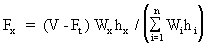
(7) The structure shall be designed to resist overturning effects caused by the earthquake forces determined in Sentence (6) and the overturning moment at level x, Mx, shall be determined using the formula,
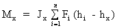
where,
Jx = 1.0 for hx ≥ 0.6hn, and
Jx = J + (1- J)(hx / 0.6hn) for hx,< 0.6hn
where,
J = base overturning moment reduction factor conforming to Table 4.1.8.11.
(8) Torsional effects that are concurrent with the effects of the forces mentioned in Sentence (6) and are caused by the following torsional moments shall be considered in the design of the structure according to Sentence (10):
(a) torsional moments introduced by eccentricity between the centres of mass and resistance and their dynamic amplification, or
(b) torsional moments due to accidental eccentricities.
(9) Torsional sensitivity shall be determined by calculating the ratio Bx for each level x according to the following equation for each orthogonal direction determined independently:
Bx = δmax / δave
where,
B = maximum of all values of Bx in both orthogonal directions, except that the Bx for one-storey penthouses with a weight less than 10% of the level below need not be considered,
δmax = maximum storey displacement at the extreme points of the structure, at level x in the direction of the earthquake induced by the equivalent static forces acting at distances ± 0.10 Dnx from the centres of mass at each floor, and
δave = average of the displacements at the extreme points of the structure at level x produced by the above mentioned forces.
(10) Torsional effects shall be accounted for as follows:
(a) for a building with B ≤1.7, by applying torsional moments about a vertical axis at each level throughout the building derived for each of the following load cases considered separately,
(i) Tx = Fx(ex + 0.10 Dnx), and
(ii) Tx = Fx(ex – 0.10 Dnx)
where Fx is the lateral force at each level determined according to Sentence (6) and where each element of the building is designed for the most severe effect of the above load cases, or
(b) for a building with B ≥1.7, in cases where IEFaSa(0.2) is equal to or greater than 0.35, by a Dynamic Analysis Procedure as specified in Article 4.1.8.12.
Editor's note
In the notes to Table-4.1.8.11., a separating space follows the footnote reference numbers; the e-Laws consolidation omits it. The footnote text is identical.
Text · e-Laws consolidated snapshot
Column 1 | Column 2 | Column 3 | Column 4 | Column 5 | Column 6 |
Sa(0.2)/Sa(2.0) | Type of Lateral Resisting System | MV For Ta ≤ 1.0 | MV For Ta ≥ 2.0 | J For Ta ≤0.5 | J For Ta ≥2.0 |
Moment-resisting frames or coupled walls(3) | 1.0 | 1.0 | 1.0 | 1.0 | |
< 8.0 | Braced frames | 1.0 | 1.0 | 1.0 | 0.8 |
Walls, wall-frame systems, other systems(4) | 1.0 | 1.2 | 1.0 | 0.7 | |
Moment-resisting frames or coupled walls(3) | 1.0 | 1.2 | 1.0 | 0.7 | |
≥8.0 | Braced frames | 1.0 | 1.5 | 1.0 | 0.5 |
Walls, wall-frame systems, other systems(4) | 1.0 | 2.5 | 1.0 | 0.4 |
Notes to Table 4.1.8.11.:
(1)For values of Mv between fundamental lateral periods, Ta, of 1.0 and 2.0 s, the product S(Ta) · Mv shall be obtained by linear interpolation.
(2)Values of J between fundamental lateral periods, Ta, of 0.5 and 2.0 s shell be obtained by linear interpolation.
(3)A “coupled wall” is a wall system with coupling beams, where at least 66% of the base overturning moment resisted by the wall system is carried by the axial tension and compression forces resulting from shear in the coupling beams.
(4)For hybrid systems, values corresponding to walls must be used or a dynamic analysis must be carried out as per Article 4.1.8.12.
4.1.8.12. — Dynamic Analysis Procedure
(1) The Dynamic Analysis Procedure shall be in accordance with one of the following methods:
(a) Linear Dynamic Analysis by either the Modal Response Spectrum Method or the Numerical Integration Linear Time History Method using a structural model that complies with the requirements of Sentence 4.1.8.3.(8), or
(b) Nonlinear Dynamic Analysis, in which case a special study shall be performed.
(2) The spectral acceleration values used in the Modal Response Spectrum Method shall be the design spectral acceleration values, S(T), defined in Sentence 4.1.8.4.(6).
(3) The ground motion histories used in the Numerical Integration Linear Time History Method shall be compatible with a response spectrum constructed from the design spectral acceleration values, S(T), defined in Sentence 4.1.8.4.(6).
(4) The effects of accidental torsional moments acting concurrently with the lateral earthquake forces that cause them shall be accounted for by the following methods:
(a) the static effects of torsional moments due to (± 0.10 Dnx)Fx at each level x, where Fx is determined from Sentence 4.1.8.11.(6)v1 or from the dynamic analysis, shall be combined with the effects determined by dynamic analysis, or
(b) if B, as defined in Sentence 4.1.8.11.(9)v1, is less than 1.7, it is permitted to use a three-dimensional dynamic analysis with the centres of mass shifted by a distance of – 0.05 Dnx and + 0.05 Dnx,
(5) The elastic base shear, Ve, obtained from a Linear Dynamic Analysis shall be multiplied by the importance factor, IE, as determined in Article 4.1.8.5., and shall be divided by RdRo, as determined in Article 4.1.8.9., to obtain the base shear, Vd.
(6) Except as required by Sentence (7), if the base shear, Vd, obtained in Sentence (5) is less than 80% of the lateral earthquake design force, V, of Article 4.1.8.11.v1, Vd shall be taken as 0.8 V.
(7) For irregular structures requiring dynamic analysis in accordance with Article 4.1.8.7., Vd shall be taken as the larger of the Vd determined in Sentence (5) and 100% of V.
(8) Except as required by Sentence (9), the values of elastic storey shears, storey forces, member forces, and deflections obtained from the Linear Dynamic Analysis shall be multiplied by Vd/Ve to determine their design values, where Vd is the base shear.
(9) For the purpose of calculating deflections, it is permitted to use a value for V based on the value for Ta determined in Clause 4.1.8.11.(3)(d)v1 to obtain Vd in Sentences (6) and (7).
Text · e-Laws consolidated snapshot
4.1.8.13. — Deflections and Drift Limits
(1) Lateral deflections of a structure shall be calculated in accordance with the loads and requirements defined in this Subsection.
(2) Lateral deflections obtained from a linear elastic analysis using the methods given in Articles 4.1.8.11.v1 and 4.1.8.12. and incorporating the effects of torsion, including accidental torsional moments, shall be multiplied by RdRo/IE to give realistic values of anticipated deflections.
(3) Based on the lateral deflections calculated in Sentence (2), the largest interstorey deflection at any level shall be limited to 0.01 hs for post-disaster buildings, 0.02 hs for schools, and 0.025 hs for all other buildings.
(4) The deflections calculated in Sentence (2) shall be used to account for sway effects as required by Sentence 4.1.3.2.(10)v1.
Text · e-Laws consolidated snapshot
4.1.8.14. — Structural Separation
(1) Adjacent structures shall either be separated by the square root of the sum of the squares of their individual deflections calculated in Sentence 4.1.8.13.(2), or shall be connected to each other.
(2) The method of connection required in Sentence (1) shall take into account the mass, stiffness, strength, ductility and anticipated motion of the connected buildings and the character of the connection.
(3) Rigidly connected buildings shall be assumed to have the lowest RdRo value of the buildings connected.
(4) Buildings with non-rigid or energy-dissipating connections require special studies.
Text · e-Laws consolidated snapshot
4.1.8.15. — Design Provisions
(1) Diaphragms and their connections shall be designed so as not to yield, and the design shall account for the shape of the diaphragm, including openings, and for the forces generated in the diaphragm due to the following cases, whichever one governs:
(a) forces due to loads determined in Articles 4.1.8.11.v1 or 4.1.8.12. applied to the diaphragm are increased to reflect the lateral load capacity of the SFRS, plus forces in the diaphragm due to the transfer of forces between elements of the SFRS associated with the lateral load capacity of such elements and accounting for discontinuities and changes in stiffness in these elements, or
(b) a minimum force corresponding to the design-based shear divided by N for the diaphragm at level x.
(2) In cases where IEFaSa(0.2) is equal to or greater than 0.35, the elements supporting any discontinuous wall, column or braced frame shall be designed for the lateral load capacity of the components of the SFRS they support.
(3) Where structures have vertical variations of RdRo satisfying Sentence 4.1.8.9.(4), the elements of the SFRS below the level where the change in RdRo occurs shall be designed for the forces associated with the lateral load capacity of the SFRS above that level.
(4) Where earthquake effects can produce forces in a column or wall due to lateral loading along both orthogonal axes, account shall be taken of the effects of potential concurrent yielding of other elements framing into the column or wall from all directions at the level under consideration and as appropriate at other levels.
(5) Except as provided in Sentence (6), the design forces need not exceed the forces determined in accordance with Sentence 4.1.8.7.(1), multiplied by RdRo.
(6) If foundation rocking is accounted for, the design forces for the SFRS need not exceed the maximum values associated with foundation rocking, provided that Rd and Ro for the type of SFRS used conform to Table 4.1.8.9. and that the foundation is designed in accordance with Sentence 4.1.8.16.(1).
Editor's note
In Clause 4.1.8.15.(1)(a), the as-filed O. Reg. 350/06 reads 'Articles 4.1.8.11. or 4.1.8.12.' (plural); this map reproduces the source as filed. The e-Laws consolidation renders the cross-reference in the singular ('Article'). This wording difference was not enacted by an amending regulation.
4.1.8.16. — Foundation Provisions
(1) Foundations shall be designed to resist the lateral load capacity of the SFRS, except that when the foundations are allowed to rock, the design forces for the foundation need not exceed those determined in Sentence 4.1.8.7.(1) using an RdRo equal to 2.0.
(2) The design of foundations shall be such that they are capable of transferring earthquake loads and effects between the building and the ground without exceeding the capacities of the soil and rock.
(3) In cases where IEFaSa(0.2) is equal to or greater than 0.35, the following requirements shall be satisfied:
(a) piles or pile caps, drilled piers, and caissons shall be interconnected by continuous ties in no fewer than two directions,
(b) piles, drilled piers, and caissons shall be embedded a minimum of 100 mm into the pile cap or structure, and
(c) piles, drilled piers, and caissons, other than wood piles, shall be connected to the pile cap or structure for a minimum tension force equal to 0.15 times the factored compression load on the pile.
(4) At sites where IEFaSa(0.2) is equal to or greater than 0.35, basement walls shall be designed to resist earthquake lateral pressures from backfill or natural ground.
(5) At sites where IEFaSa(0.2) is greater than 0.75, the following requirements shall be satisfied:
(a) piles, drilled piers, or caissons shall be designed and detailed to accommodate cyclic inelastic behaviour when the design moment in the element due to earthquake effects is greater than 75% of its moment capacity, and
(b) spread footings founded on soil defined as Site Class E or F shall be interconnected by continuous ties in no fewer than two directions.
(6) Each segment of a tie between elements that is required by Clauses (3)(a) or (5)(b) shall be designed to carry by tension or compression a horizontal force at least equal to the greatest factored pile cap or column vertical load in the elements it connects, multiplied by a factor of 0.10 IEFaSa(0.2), unless it can be demonstrated that equivalent restraints can be provided by other means.
(7) The potential for liquefaction of the soil and its consequences, such as significant ground displacement and loss of soil strength and stiffness, shall be evaluated based on the ground motion parameters referenced in Subsection 1.1.2. and shall be taken into account in the design of the structure and its foundations.
Editor's note
In Sentence 4.1.8.16.(6), the as-filed O. Reg. 350/06 reads 'required by Clauses (3)(a) or (5)(b)' (plural); this map reproduces the source as filed. The e-Laws consolidation renders the cross-reference in the singular ('Clause'). This wording difference was not enacted by an amending regulation.
4.1.8.17. — Elements of Structures, Non-structural Components and Equipment
(1) Except as provided in Sentences (2) and (8), elements and components of buildings described in Table 4.1.8.17. and their connections to the structure shall be designed to accommodate the building deflections calculated in accordance with Article 4.1.8.13. and the element or component deflections calculated in accordance with Sentence (10), and shall be designed for a lateral force, VP, applied through the centre of mass of the element or component that is equal to:
Vp= 0.3FaSa(0.2) IESpWp
where,
Fa = as defined in Table 4.1.8.4.B.,
Sa(0.2) = spectral response acceleration value at 0.2 s, as defined in Sentence 4.1.8.4.(1),
IE = importance factor for the building, as defined in Article 4.1.8.5.,
Sp = CpArAx/Rp (the maximum value of Sp shall be taken as 4.0 and the minimum value of Sp shall be taken as 0.7), where
Cp = element or component factor from Table 4.1.8.17.,
Ar = element or component force amplification factor from Table 4.1.8.17.,
Ax = height factor (1 + 2 hx / hn),
Rp = element or component response modification factor from Table 4.1.8.17., and
Wp = weight of the component or element.
(2) For buildings other than post-disaster buildings, where IEFaSa(0.2) is less than 0.35, the requirements of Sentence (1) need not apply to Categories 6 through 21 of Table 4.1.8.17.
(3) The values of Cp in Sentence (1) shall conform to Table 4.1.8.17.
(4) For the purpose of applying Sentence (1) and Categories 11 and 12 of Table 4.1.8.17., elements or components shall be assumed to be flexible or flexibly connected unless it can be shown that the fundamental period of the element or component and its connection is less than or equal to 0.06 s, in which case the element or component is classified as being rigid or rigidly connected.
(5) The weight of access floors shall include the dead load of the access floor and the weight of permanent equipment, which shall not be taken as less than 25% of the floor live load.
(6) When the mass of a tank plus its contents is greater than 10% of the mass of the supporting floor, the lateral forces shall be determined by rational analysis.
(7) Forces shall be applied in the horizontal direction that results in the most critical loading for design, except for Category 6 of Table 4.1.8.17., where the forces shall be applied up and down vertically.
(8) Connections to the structure of elements and components listed in Table 4.1.8.17. shall be designed to support the component or element for gravity loads, shall conform to the requirements of Sentence (1), and shall also satisfy these additional requirements:
(a) friction due to gravity loads shall not be considered to provide resistance to seismic forces,
(b) Rp for non-ductile connections, such as adhesives or power actuated fasteners, shall be taken as 1.0,
(c) Rp for anchorage using shallow expansion, chemical, epoxy or cast-in place anchors shall be 1.5, where shallow anchors are those with a ratio of embedment length to diameter of less than 8,
(d) power-actuated fasteners and drop-in anchors shall not be used for tension loads,
(e) connections for non-structural elements or components of Categories 1, 2 or 3 of Table 4.1.8.17. attached to the side of a building and above the first level above grade shall satisfy the following requirements:
(i) for connections where the body of the connection is ductile, the body shall be designed for values of CP, Ar and Rp given in Table 4.1.8.17., and the fasteners, such as anchors, welds, bolts and inserts, shall also be designed for values of Cp and Ar given in this Table, and Rp = 1.0, and
(ii) connections where the body of the connection is not ductile shall be designed for values of Cp=2.0, Rp =1.0 and Ar given in Table 4.1.8.17., and
(f) for the purpose of applying Clause (e), a ductile connection is one where the body of the connection yields at its design load.
(9) Floors and roofs acting as diaphragms shall satisfy the requirements for diaphragms stated in Article 4.1.8.15.
(10) Lateral deflections of elements or components shall be based on the loads defined in Sentence (1) and lateral deflections obtained from an elastic analysis shall be multiplied by Rp/IE to give realistic values of the anticipated deflections.
(11) The elements or components shall be designed so as not to transfer to the structure any forces unaccounted for in the design, and rigid elements such as walls or panels shall satisfy the requirements of Sentence 4.1.8.3.(6).
(12) Seismic restraint for suspended equipment, pipes, ducts, electrical cable trays, etc. shall be designed to meet the force and displacement requirements of this Article and be constructed in a manner that will not subject hanger rods to bending.
(13) Isolated suspended equipment and components, such as pendant lights, maybe designed as a pendulum system provided that adequate chains or cables capable of supporting 2.0 times the weight of the suspended component are provided and the deflection requirements of Sentence (11) are satisfied.
Editor's note
This map follows the as-filed text of O. Reg. 350/06, which reads 'firefighting fluids' (one word) in Table 4.1.8.17. The e-Laws consolidation editorially renders it as 'fire fighting' (two words); no amending regulation makes this change.
Text · e-Laws consolidated snapshot
| Column 1 | Column 2 | Column 3 | Column 4 | Column 5 |
| Category | Part or portion of Building | Cp | Ar | Rp |
| 1 | All exterior and interior walls except those in Category 2 or 3(1) | 1.00 | 1.00 | 2.50 |
| 2 | Cantilever parapet and other cantilever walls except retaining walls(1) | 1.00 | 2.50 | 2.50 |
| 3 | Exterior and interior ornamentations and appendages(1) | 1.00 | 2.50 | 2.50 |
| 4 | Floors and roofs acting as diaphragms(2) | - | - | 2.50 |
| 5 | Towers, chimneys, smokestacks and penthouses when connected to or forming part of a building | 1.00 | 2.50 | 2.50 |
| 6 | Horizontally cantilevered floors, balconies, beams, etc. | 1.00 | 1.00 | 2.50 |
| 7 | Suspended ceilings, light fixtures and other attachments to ceilings with independent vertical support | 1.00 | 1.00 | 2.50 |
| 8 | Masonry veneer connections | 1.00 | 1.00 | 1.50 |
| 9 | Access floors | 1.00 | 1.00 | 2.50 |
| 10 | Masonry or concrete fences more than 1.8 m tall | 1.00 | 1.00 | 2.50 |
| 11 | Machinery, fixtures, equipment, ducts and tanks (including contents) |
|
|
|
|
| that are rigid and rigidly connected(3) | 1.00 | 1.00 | 1.25 |
|
| that are flexible or flexibly connected(3) | 1.00 | 2.50 | 2.50 |
| 12 | Machinery, fixtures, equipment, ducts and tanks (including contents) containing toxic or explosive materials, materials having a flash point below 38°C or firefighting fluids |
|
|
|
|
| that are rigid and rigidly connected(3) | 1.50 | 1.00 | 1.25 |
|
| that are flexible or flexibly connected(3) | 1.50 | 2.50 | 2.50 |
| 13 | Flat bottom tanks (including contents) attached directly to a floor at or below grade within a building | 0.70 | 1.00 | 2.50 |
| 14 | Flat bottom tanks (including contents) attached directly to a floor at or below grade within a building containing toxic or explosive materials, materials having a having a flash point below 38°C or firefighting fluids | 1.00 | 1.00 | 3.00 |
| 15 | Pipes, ducts, cable trays (including contents) | 1.00 | 1.00 | 3.00 |
| 16 | Pipes, ducts (including contents) containing toxic or explosive materials | 1.50 | 1.00 | 3.00 |
| 17 | Electrical cable trays, bus ducts, conduits | 1.00 | 2.50 | 5.00 |
| 18 | Rigid components with ductile material and connections | 1.00 | 1.00 | 2.50 |
| 19 | Rigid components with non-ductile material or connections | 1.00 | 1.00 | 1.00 |
| 20 | Flexible components with ductile material and connections | 1.00 | 2.50 | 2.50 |
| 21 | Flexible components with non-ductile material or connections | 1.00 | 2.50 | 1.00 |
Notes to Table 4.1.8.17.:
(1)See Sentence 4.1.8.17.(8).
(2)See Sentence 4.1.8.17.(9).
(3)See Sentence 4.1.8.17.(4).
Provenance
OBC 1997 · renumbered from 4.1.9. — Pro
Base · O. Reg. 350/06 · ext← current
Original — base regulation
OBC 2012 · continues as 4.1.8. — Pro